What if a 1% measurement deviation could affect a utility’s annual energy balance by more than €100,000? Laser-based on-site calibration allows district heating operators to verify large flow meters under real operating conditions – without shutting down the plant. Drawing on more than 240 field calibrations, this article shows how accurate measurement data can strengthen billing, efficiency, optimisation, and operational confidence.
By Ulrich Müller, OPTOLUTION Messtechnik GmbH
Published in Hot Cool, edition no. 5/2026 | ISSN 0904 9681 |
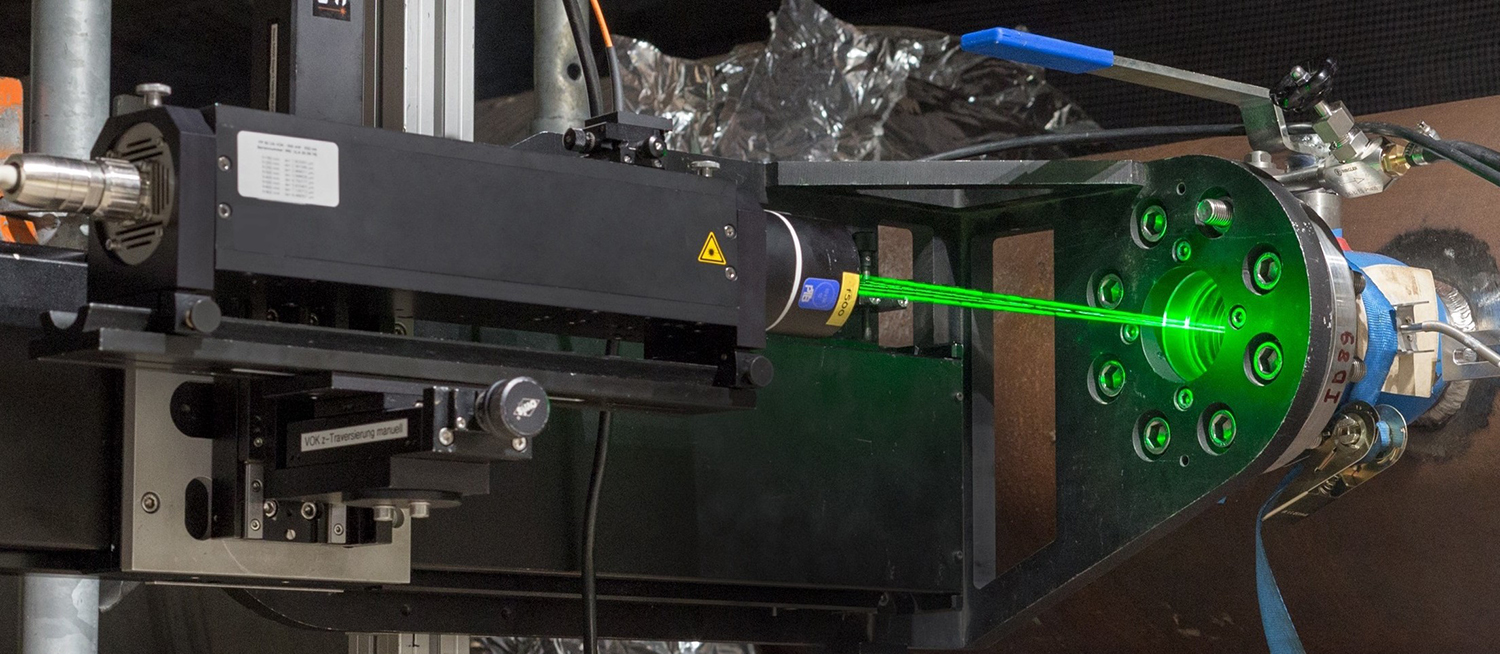
Laser-based on-site calibration enables utilities to verify the performance of installed large flow meters under real operating conditions without interrupting plant operation. By combining accredited laser metrology with practical field deployment, the method improves confidence in measurement data, supports network optimisation and delivers measurable economic benefits.
Every percentage point counts.
Accurate flow measurement underpins customer billing, energy balancing, efficiency calculations and regulatory reporting. As district heating (DH) networks become larger and more complex, operators increasingly depend on reliable measurement data throughout the entire service life of their assets. Many large flow meters, however, remain in operation for decades after commissioning without being recalibrated under real operating conditions.
For a typical 50 MW DH metering point operating over 150 heating days per year with a heat price of €60/MWh, a measurement deviation of only 1% corresponds to an annual energy balance deviation of approximately €108,000. Reliable flow measurement is therefore not merely a metrological issue but a technical, operational and commercial requirement.
Why factory calibration is not enough
Factory calibration is performed under controlled laboratory conditions with well-defined flow profiles and traceable reference facilities. In service, however, pipe bends, valves, pumps, reducers, tees, and changing operating conditions frequently create asymmetric or swirling flow profiles that differ significantly from laboratory conditions. Consequently, factory calibration validates the instrument itself but cannot fully represent the performance of the complete measuring system after installation.
Conventional recalibration requires removing the meter and transporting it to an accredited laboratory. For large transmission pipelines, this often means shutdowns, bypass installations, and considerable costs. As a result, operators often postpone recalibrations or do not perform them at all. Even if performed, calibration conditions almost always differ from operational ones and therefore always introduce additional unknowns in flow meter reliability.
Advantages of laser optical on-site calibration
- Calibration without interrupting plant operation.
- Verification under real operating conditions.
- Independent of flow meter technology.
- Accredited according to EN ISO/IEC 17025.
- Applicable to DN100–DN1200.
- Traceable verification of the complete measuring system.
- Suitable for DH, district cooling and water networks.
Bringing the calibration to the pipeline
The On-Site Calibration (OSC) method reverses this concept by bringing the reference measurement system directly to the installed flow meter. The technology is based on Laser Doppler Velocimetry (LDV), which measures local flow velocity from the Doppler shift of laser light scattered by tracer particles (Figure 2).
Optical access is established using a specially developed full-bore ball valve, hot tapping, and a pressure window assembly. Calibration is therefore performed while the pipeline remains fully operational, eliminating the need for service interruptions.
Measuring the real flow profile
An automated traversing system moves the laser probe across the pipe diameter, recording approximately 150 local velocity measurements per profile (Figure 2). During this velocity scan, the meter-under-test values are logged at the highest possible temporal resolution. The flow meter measurement error is calculated by comparing the calculated LDV volume flow with the time-averaged volume flow of the meter.
Instead of relying on a single measuring point, the OSC method captures the complete velocity distribution across the pipe cross-section. The resulting profile is used to calculate the reference volume flow while simultaneously revealing asymmetry and other hydraulic characteristics. Figure 3 shows typical measured profiles and the results graph from a calibration. The issued calibration certificate also includes information about the meter under test and the measurement conditions.
Probe positioning, data acquisition and measurement sequences are fully automated after parameterisation. An optical revolver enables automatic adjustment of the measuring optics for different operating conditions, while remote monitoring allows long measurement campaigns to continue overnight without permanent operator attendance.
Calibrations are typically performed at several operating points to assess meter performance across its working range. Because LDV measures velocity directly, it is independent of the measuring principle of the installed flow meter and can therefore be applied to electromagnetic, ultrasonic, orifice flow meters and other meter types.
Reliable reference measurements under fluctuating conditions
Unlike laboratory calibrations, field measurements are performed under continuously changing operating conditions. Flow rate fluctuations caused by consumer demand or pump operation are compensated by normalising the LDV measurements with data from an independently installed ultrasonic clamp-on flow meter. This approach keeps the reference measurement independent of the flow meter under test [1]. It relies only on the proven linearity of the clamp-on instrument, which is specifically qualified for this task.
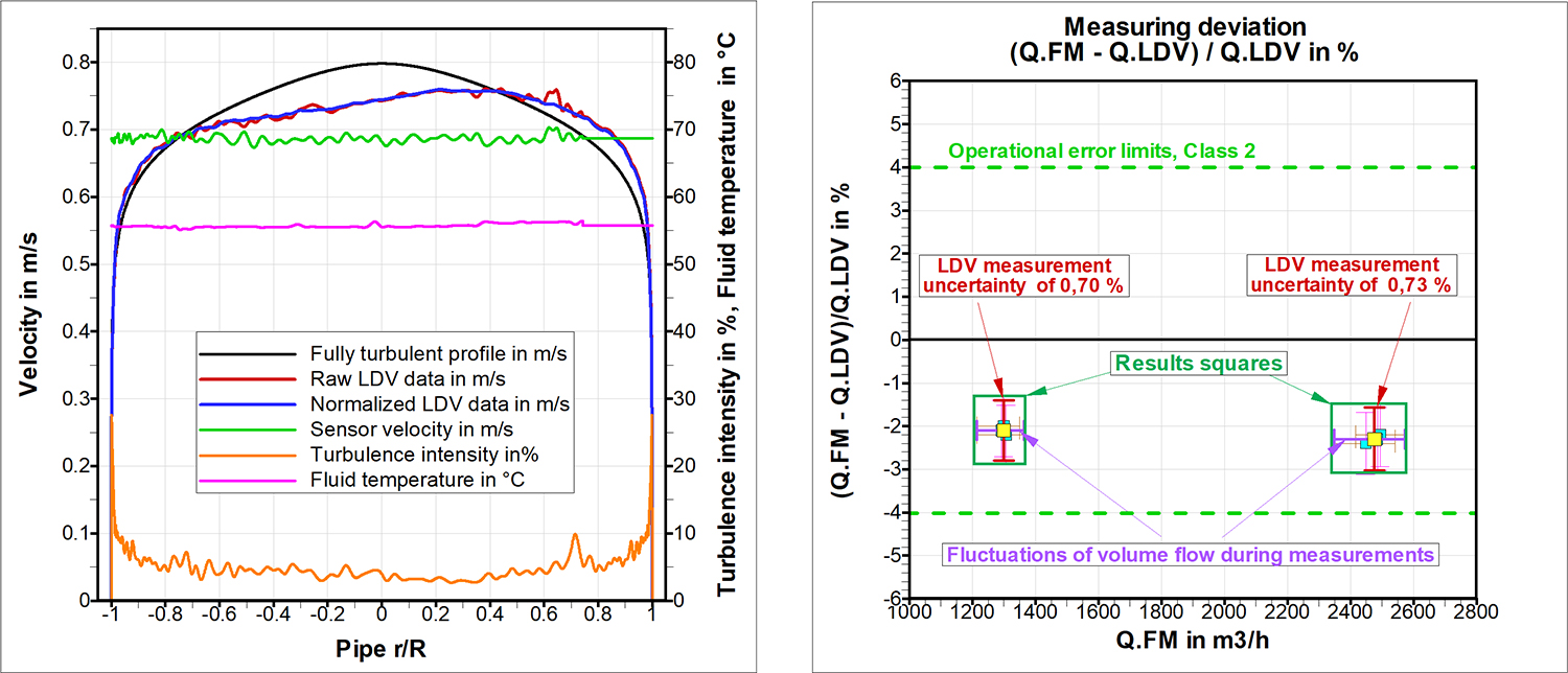
Figure 3: Measured profiles (profile class “slightly disturbed”) and results diagram (profile class “fully developed”) Measured profiles (profile class “slightly disturbed”) and results diagram (profile class “fully developed”)
Accredited measurement quality
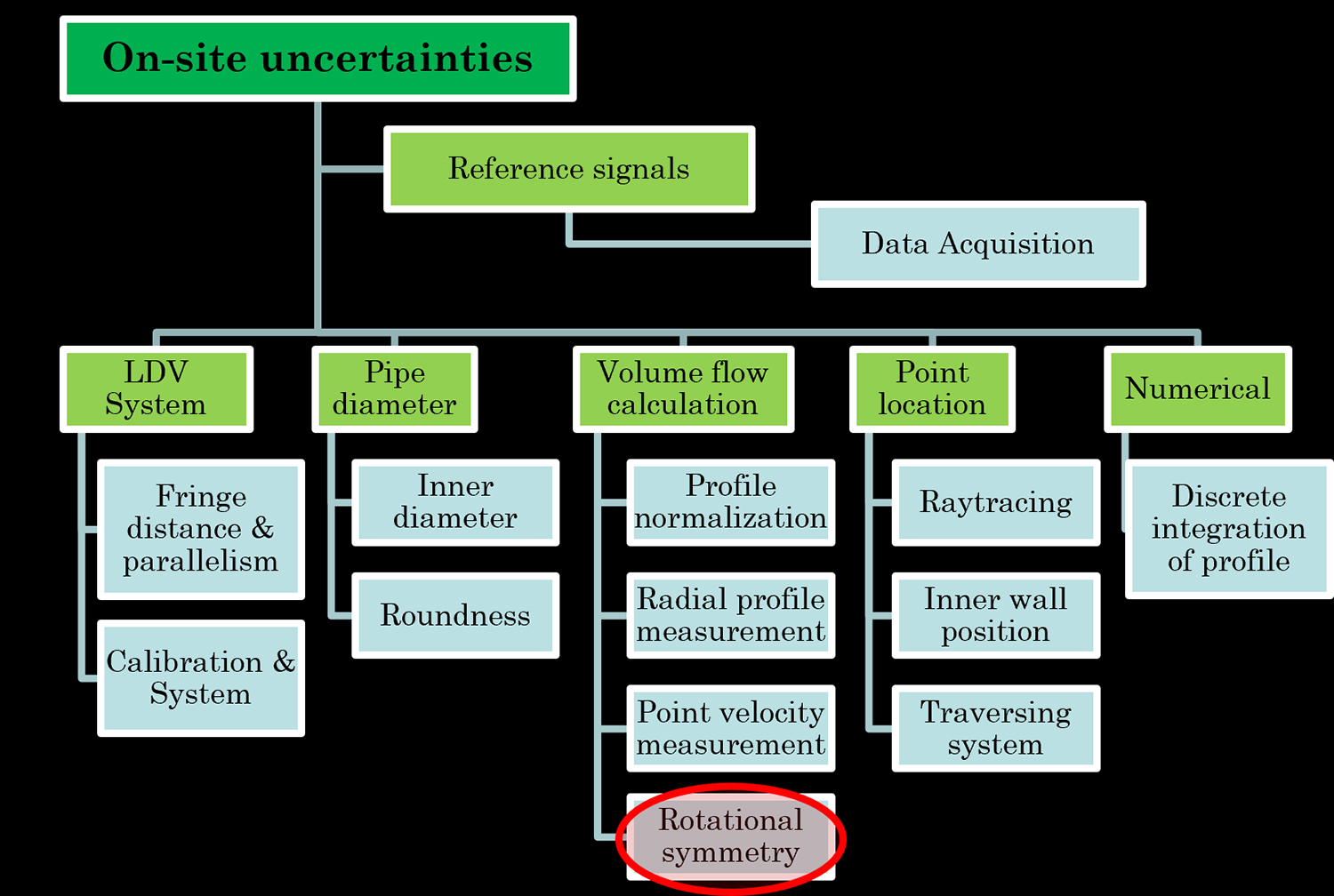
Accurate field calibration requires not only precise instrumentation but also a transparent uncertainty evaluation. The OSC method is accredited according to EN ISO/IEC 17025 [2]. To achieve the credibility and traceability required for accreditation, a wide range of uncertainties from multiple sources (see Figure 4) needed to be quantified and put together in an extensive uncertainty budget. The dominant uncertainty contribution originates from the velocity profile at the measuring location.
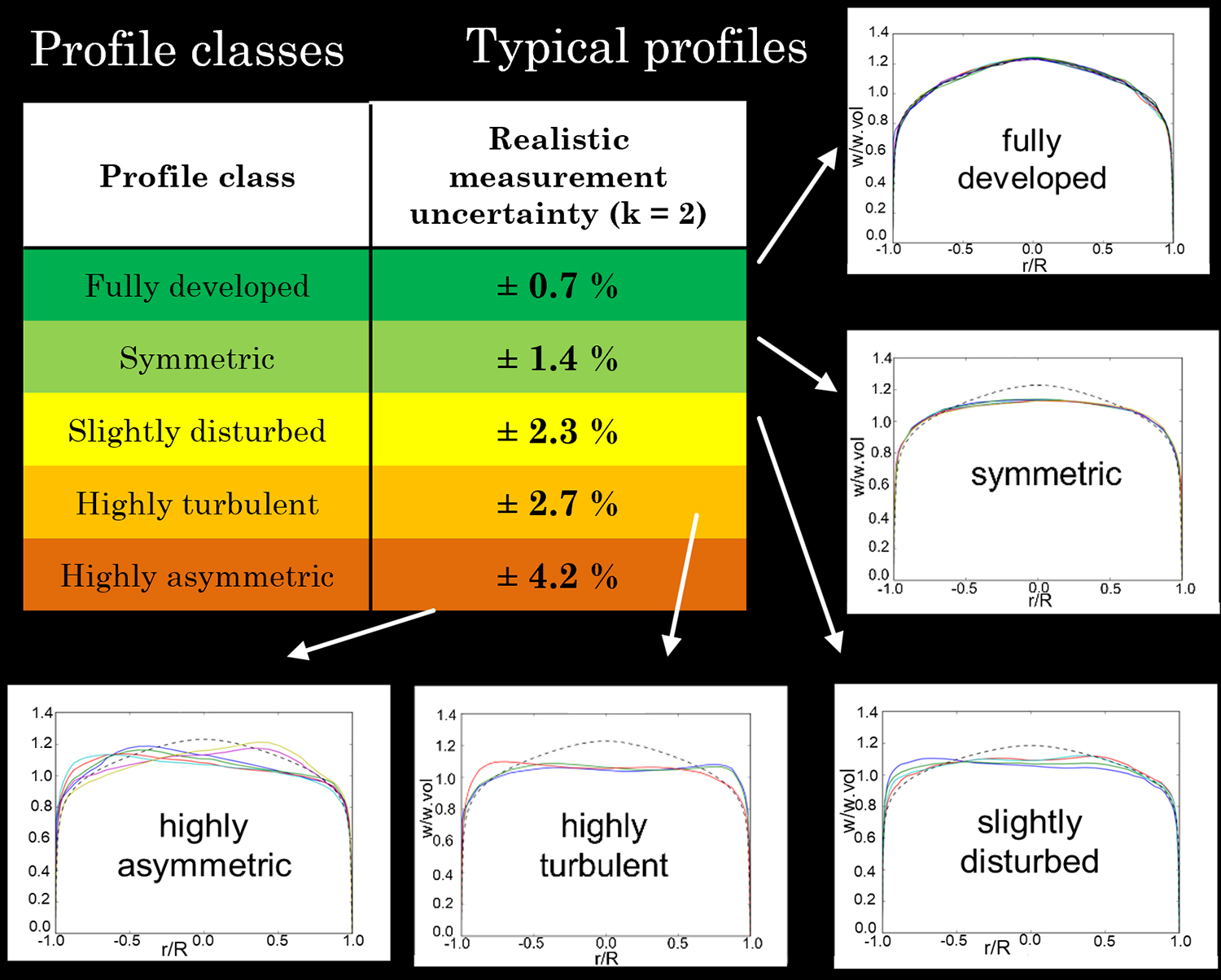
To quantify this influence, CFD simulations were combined with high-precision LDV measurements in a publicly funded research project [3]. Mathematical analysis of the profile allows every measurement to be assigned to one of several characteristic flow classes, each associated with a realistic measurement uncertainty [4].
Figure 5 shows the achievable total measurement uncertainties for each profile class. The minimum uncertainty for the “fully developed” profile class consists only of non-profile-related contributions.
Practical experience
More than 240 large flow meters have been calibrated in Germany, Austria, Switzerland and Australia on pipelines ranging from DN 100 to DN 1200 (Figure 6). The operating conditions of the measurements ranged from 5°C to 150°C in fluid temperature, fluid pressures ranging from 2 bar to 18 bar, and pipe sizes between DN 100 and DN 1200.
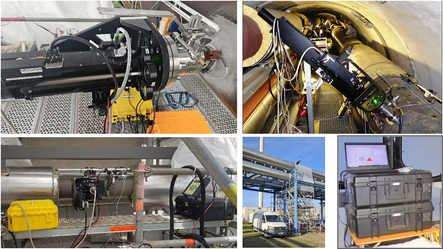
The OSC method is also often used as a recalibration tool for flow sensors which were subsequently added as instrumentation to the grid lines. Because those flow sensors are often ultrasonic clamp-on or other comparatively easy-to-install flow meters, they often lack the needed measurement precision. An additional calibration after mounting can reduce the measurement uncertainty of these flow sensors by several percentage points.
Of the 241 flow sensors calibrated to date, 45 showed measurement deviations of more than 4%, after accounting for the inherent uncertainty of the OSC method. This means approximately 19% of all inspected flow sensors show significant deviations from their initial test-rig calibrations (Figure 7). In addition, approximately 5 % of the submitted flow sensors could not be calibrated due to faulty measurement characteristics.
At the same time, most meters showed good agreement with their original calibration, giving operators independent evidence that their installations continued to perform within specification.
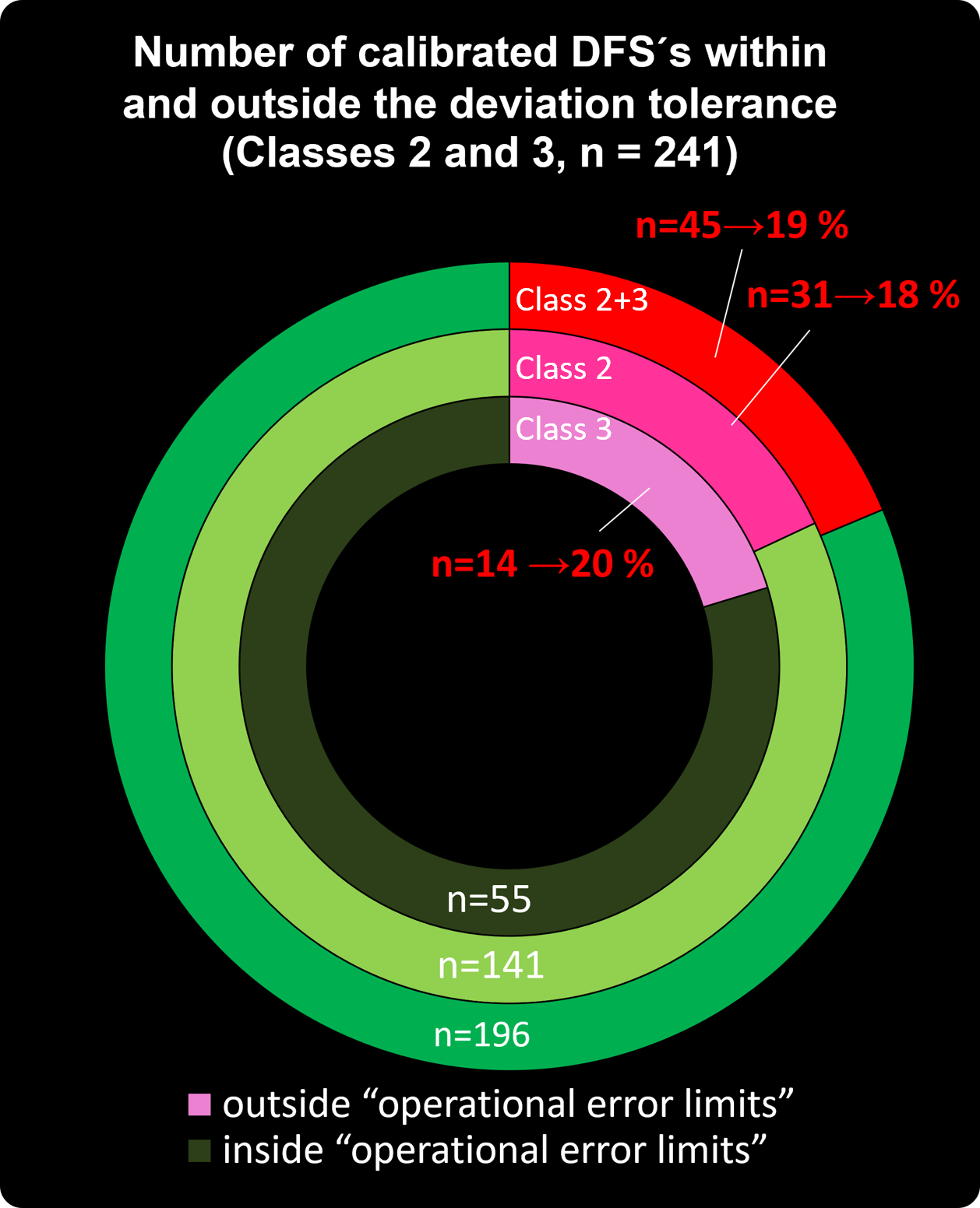
Figure 7: Results from more than 240 accredited on-site calibrations.
Benefits for utilities
On-site calibration improves confidence in customer billing, energy balances, efficiency assessments and regulatory reporting. It supports network optimisation, verifies newly installed clamp-on flow meters under real operating conditions and provides traceable evidence of the performance of the complete measuring system rather than the instrument alone. Because calibration is performed without interrupting plant operation, the method minimises operational impact while maximising practical value.
Key benefits for utilities:
- Higher confidence in customer billing. Reliable energy balances under real operating conditions.
- Reduced operational risk without plant shutdown.
- Traceable calibration results for audits and quality assurance.
- Improved efficiency through verified measurement data.
Conclusion
Laser-based on-site calibration bridges the gap between laboratory calibration and everyday operation. By combining accredited laser metrology, automated field measurements and rigorous uncertainty evaluation, utilities can verify the accuracy of installed large flow meters under real operating conditions. As district heating systems become increasingly digital and efficiency-driven, reliable measurement data will remain a key prerequisite for sound technical, commercial and regulatory decisions.
Abbreviations
FM Flow meter
LDV Laser Doppler velocimetry
OSC On-site calibration
References
[1] ISO 3966:2008. Measurement of fluid flow in closed conduits – Velocity area method using Pitot static tubes. ISO Standard, 2008.
[2] EN ISO/IEC 17025:2018-03. General requirements for the competence of testing and calibration laboratories. ISO Standard, 2018-03.
[3] AGFW – Der Energieeffizienzverband für Wärme, Kälte und KWK e.V. “EnEff. Wärme – Energieeffizienz in der Fernwärme durch Vor-Ort-Kalibrierung von Durchflussmessgeräten – Kopplung von laseroptischen und numerischen Verfahren”. Joint Final Report by the Partners ILA R&D GmbH, OPTOLUTION Messtechnik GmbH, Physikalische-Technische Bundesanstalt, Technische Universität Berlin, VATTENFALL Europe Wärme AG, AGFW, Forschung und Entwicklung, Issue 46, Frankfurt/Main, 2018.
[4] Müller, U.; Dues, M.; Hübert, W.; Rautenberg, C.: Improving operational efficiency of power plants through on-site calibration of flow sensors.
16th International Symposium on District Heating and Cooling, DHC2018, 9–12 September 2018, Hamburg, Germany. DOI 10.1016/j.egypro.2018.08.183
For further information, please contact Dr. Ulrich Müller, mueller@optolution.com
“Improving operational efficiency through on-site calibration of flow meters” was published in Hot Cool, edition no. 5/2026. You can download the article here:
Did you find this article useful?
Subscribe to the HOT|COOL newsletters for free and get insightful articles on a variety of topics delivered to your inbox twice a month!